This post is part of a series:
- Introduction
- Protocols
- Internet Protocol
- User Datagram Protocol
- Transmission Control Protocol
- Domain Name System
Sorry for the delay in publishing this! I actually started off the year with ambitious plans to blast through some writing and have a nice little pipeline of finished articles ready to deploy. What actually happened was that I caught Covid. Without meaning to sound like Toby Young, for me it was fortunately just a bad case of the flu. It did mean my capacity for writing about networking protocols was limited, but now I’m back in action!
Introduction
Networking was one of the first computer science topics I ever contemplated. What I wanted to know was: how does a computer know what to do with the messages it receives from the network?
If each incoming packet is a long sequence of bytes, how does the receiver know what each byte means? Perhaps the packet includes some kind of identifier that indicates its type. How, then, does the receiver find and decode the identifier? To know where the identifier is and what it means, the receiver needs to know the packet’s format. We are back to the original problem!
I found the answers to my questions in the computer networking bible, TCP/IP Illustrated: Volume 1. Though it did give me the answers I wanted, it also gave me approximately 1,000 times more detail than I really needed. In this post series, I hope to be more succinct.
The answer was revelatory: the computer doesn’t really “know” what it’s receiving. It merely assumes that the message is in the right format and applies the rules defined by the programmer. Assuming everyone’s playing by the same set of rules, everything should work out correctly.
This is a deep idea and reappears frequently in computer science. Remember, every time you see a computer do something that seems intelligent, all that’s really happening is that lots of simple, dumb components are doing their simple, dumb thing according to a set of rules. In networking, the set of rules is known as a protocol.
Establishing the rules of the game
In order to coordinate behaviour, whether between people or computers, both parties need a shared understanding of the rules. In a game of football, everyone on the pitch understands the rules and so the match can play out smoothly without having to negotiate every interaction. As I described in the previous post, greetings are a good example of how behavioural protocols allow humans to coordinate their behaviour without explicit instruction.
For computer networking, we need to explicitly create that common foundation by programming every machine on the network to communicate according to the same rules: a protocol.
Protocols are defined by a specification for how messages should be formatted and how they should be interpreted. Computers on a network can successfully communicate if they all run programs that correctly implement the same protocol. Note that they don’t have to be the same program. My iPhone isn’t running the same software as my laptop, but both programs implement the same protocol and so communication is possible.
If everyone behaves themselves and operates according to the protocol, things will work out. If someone misbehaves and sends out a malformed message or responds in an unexpected way, the receivers won’t know how to handle it. In the best case, the receiver will reject the message and possibly notify the sender. In the worst case, the receiver will attempt to process the invalid input, putting itself into an invalid state and potentially exposing a security weakness (see here for one example of many).
The Internet protocol suite
We expect a lot from Internet communication. Try opening your browser’s developer tools and watch the “network” tab while you click around. What you’ll see is that your browser dispatches a request and then, after some time period, the response appears complete, in order and with no corruption.
Handling all of that in a single protocol would be very complex and would make the protocol very specific. What would happen when we had a slightly different use case? When streaming video, for instance, we want to send a large amount of data as quickly as possible but it doesn’t matter if the occasional frame goes missing. We’d have to write an entirely different protocol for that use case and then we’d have no way of knowing which protocol to expect.
As ever, when faced with great complexity, we can make it more manageable by breaking down the problem. The solution is to layer multiple protocols on top of each other to create a protocol stack. Each layer provides part of the overall network functionality and forms a consistent, common communication basis for the layers above.
This modularisation creates a highly effective separation of concerns. The layer that’s responsible for sending a single packet across the Internet is completely separate to the layer that splits a long message into multiple packets and ensures their reliable, in order delivery. They are both separate to the layer that tells the receiver what to do with the delivered message.
The Internet is designed as a protocol stack known as the Internet protocol suite. The most important protocols in the suite are the Transmission Control Protocol (TCP) and the Internet Protocol (IP), known together as TCP/IP.
The Internet protocol suite has four layers, shown below. The layers closest to the user are at the top and the layers closest to the network hardware are at the bottom. You’ll also come across a more general networking stack model known as the OSI model (after Open Systems Interconnection, though you’ll never need to know that). It has seven layers. I’ve included each layer’s corresponding OSI layer number, just because you’ll occasionally see people say things like “layer seven load balancer”.
| Internet layer | OSI number | Common protocols |
|---|---|---|
| Application | 7 | HTTP, SMTP, FTP |
| Transport | 4 | TCP, UDP |
| Internet | 3 | IP |
| Link | 1/2 | Ethernet |
Multiple protocols exist at each layer. Protocols on the same layer might provide quite different functionality but they will all operate at roughly the same level of abstraction. As long as the sender and receiver are using the same protocol on the underlying layer, they will be able to coordinate behaviour on the upper layers.
The link layer handles connections between hosts on the same physical network (e.g. WiFi, Ethernet).
The internet layer handles communication across network boundaries (remember, internetwork communication!). IP will attempt, but not guarantee, to deliver packets across network boundaries but it doesn’t do anything else. Though obviously fundamentally important, IP by itself is often inadequate.
For more sophisticated functionality, we need to move up to the transport layer. Protocols here provide additional “services” to the communicating hosts. For example, TCP implements the abstraction of a reliable, two-way connection on top of IP’s unreliable, single packet delivery.
The application layer, predictably enough, provides application-specific behaviour. HTTP handles web requests, SMTP handles email, FTP handles files and so on.
Before moving on, it’s interesting to note that the transport and application layers are only implemented on the communicating hosts. The intermediate routers only operate at the internet layer and so only see IP packets coming and going. The Internet, as a communication network, is deeply unconcerned about what you use it for.
Get the free 45-page CS roadmap
Subscribe and I'll send you a free, 45-page roadmap through computer science — what to learn, in what order, and what to skip — plus the occasional CS deep dive.
No spam. Unsubscribe anytime.
Headers and payloads
Let’s look at what “packets” actually are and how protocols work with them. Sometimes protocols use a different term for their packets. Ethernet calls them “frames” and TCP calls them “segments”. I hope you can forgive my imprecision by simply saying “packet”, but I think it’s more straightforward.
An Internet transmission begins with the payload: the message that the sending application wants to transmit. Starting from the top of the stack, each layer takes the payload, wraps some metadata around it and passes the metadata-payload bundle down to the next layer. Each layer treats the packet from the layer above as an opaque payload and does not modify it. This is an example of encapsulation. The combined metadata and payload of one layer forms the payload of the next:
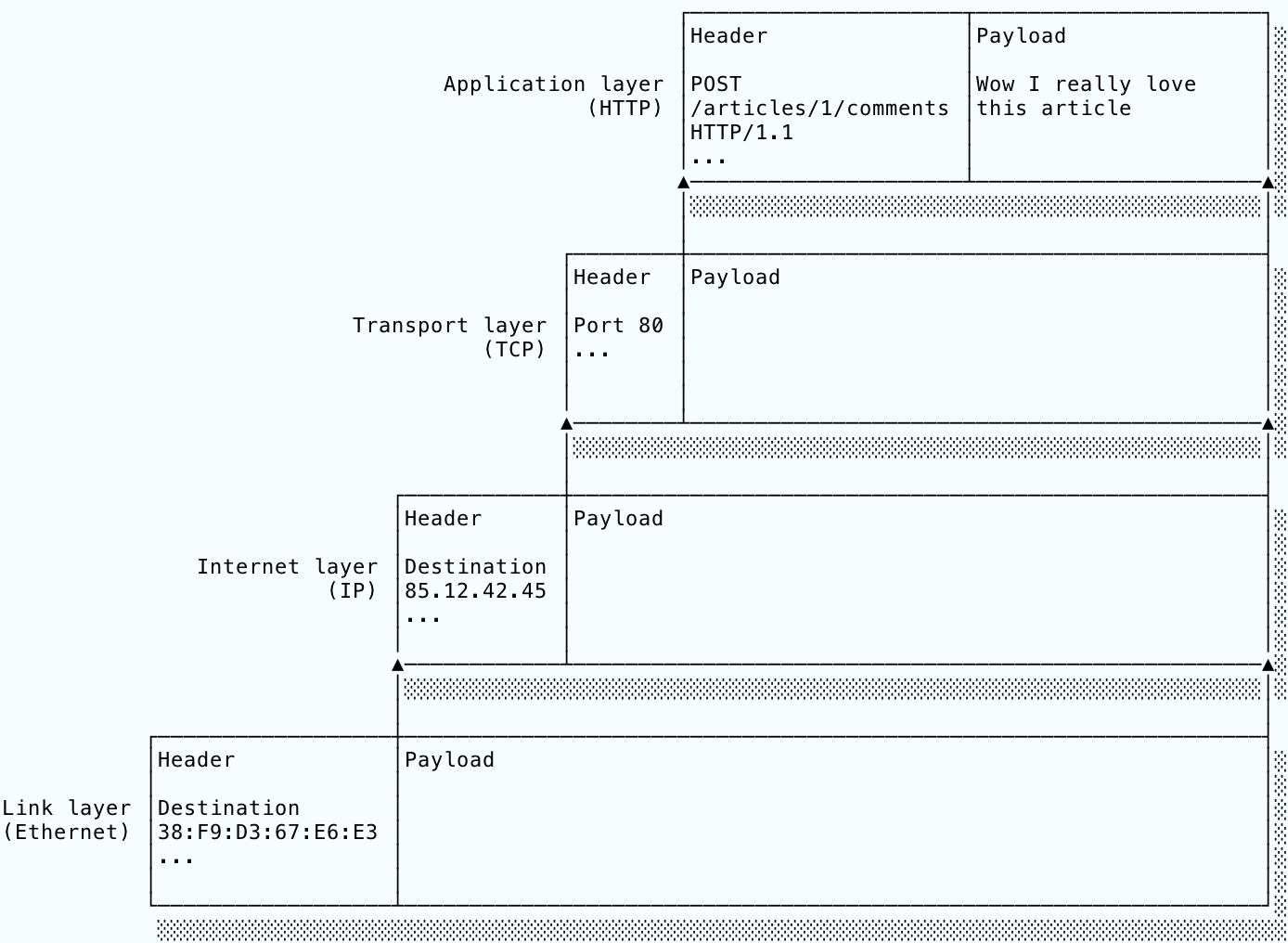
On the receiving host, the process works in reverse. Going upwards, the protocol at each layer uses the metadata to implement its functionality. For example, TCP will break a long message into multiple IP packets, number them and send them out. The receiver’s TCP implementation will use the incoming packets’ numbering to arrange them into the correct order and request any missing packets from the sender. The metadata will also include a field identifying the payload’s protocol so that the unwrapped payload can be dispatched to the correct protocol in the layer above. As the packet moves up through the layers, it sheds its layers of metadata until the application finally receives the original payload.
The code that performs all of this work is (somewhat confusingly) known as the operating system’s networking stack and generally resides in the kernel.
I’ve been a bit coy with the term “metadata”. Remember that each protocol’s metadata must follow a defined format so that other computers using the same protocol can correctly interpret the data. This formatted metadata is called the protocol’s header.
A header is a sequence of bytes conceptually divided into fields, just as an array is a contiguous block of memory conceptually divided into elements. The protocol defines the size and meaning of each field. The header must contain all the information necessary for the protocol to deliver its functionality.
Let’s look at Ethernet as an example. Remember that Ethernet is a link layer protocol responsible for delivering packets to hosts connected to the same physical network. Its header format is simple because the protocol doesn’t do a huge amount. Every packet (technically “frame”, but YOLO) begins with a seven byte “preamble” of alternating ones and zeroes. That’s how the receiving hardware can identify the incoming data as an Ethernet packet. Then comes the header, structured like so:
 0                   1                   2                   3                   4
 0 1 2 3 4 5 6 7 8 9 0 1 2 3 4 5 6 7 8 9 0 1 2 3 4 5 6 7 8 9 0 1 2 3 4 5 6 7 8 9 0 1 2 3 4 5 6 7
+-+-+-+-+-+-+-+-+-+-+-+-+-+-+-+-+-+-+-+-+-+-+-+-+-+-+-+-+-+-+-+-+-+-+-+-+-+-+-+-+-+-+-+-+-+-+-+-+
|                                      Destination Address                                      |
+-+-+-+-+-+-+-+-+-+-+-+-+-+-+-+-+-+-+-+-+-+-+-+-+-+-+-+-+-+-+-+-+-+-+-+-+-+-+-+-+-+-+-+-+-+-+-+-+
|                                         Source Address                                        |
+-+-+-+-+-+-+-+-+-+-+-+-+-+-+-+-+-+-+-+-+-+-+-+-+-+-+-+-+-+-+-+-+-+-+-+-+-+-+-+-+-+-+-+-+-+-+-+-+
|           EtherType           |                                                               |
+-+-+-+-+-+-+-+-+-+-+-+-+-+-+-+-+                                                               +
|                                                                                               |
+                                            Payload                                            +
|                                                                                               |
+-+-+-+-+-+-+-+-+-+-+-+-+-+-+-+-+-+-+-+-+-+-+-+-+-+-+-+-+-+-+-+-+-+-+-+-+-+-+-+-+-+-+-+-+-+-+-+-+
(diagram generated with Protocol and sadly breaking my formatting)
We see the first six bytes (48 bits) are the destination address, followed by another six bytes for the source address. These addresses are known as MAC address and are uniquely assigned to the network card. Normally, your device’s MAC address doesn’t change. Since Ethernet operates at the link layer, the lowest level of the Internet protocol suite, we would expect that Ethernet operates close to the hardware in this way. We’ll see in a later post how IP addresses are a higher-level abstraction.
The EtherType field is interesting. If its value is less than or equal to 1500, the Ethernet protocol specifies that it should be interpreted as the payload size (thus setting an upper limit on Ethernet packet size). If it is greater that 1500, its value should instead be interpreted as an identifier for the payload’s internet layer protocol. For example, an EtherType of 0x0800 (2048 in decimal), tells the receiver that the payload is an IP packet. That is how the receiver knows which protocol to pass the payload on to. A final error-checking value (not shown) lets the receiver verify that the message did not get corrupted during transmission.
Conclusion
Protocols are rules for behaviour and communication. Provided every party follows the same protocol, they can communicate without explicit coordination. Two computers operating the same protocol can therefore communicate.
The Internet uses a stack of protocols to provide modularisation and reduce complexity. At each of the four layers in the stack there are multiple protocols available. Web requests will most likely use Ethernet/WiFi on the link layer, IP on the internet layer, TCP on the transport layer and HTTP on the application layer. Each protocol provides different behaviour, though protocols on the same layer generally operate at the same level of abstraction. The link layer is closest to the hardware and the application layer is closest to the user.
Protocols wrap their payloads in protocol-specific headers that provide useful metadata to the receiving machine’s protocol implementation, enabling whatever functionality the protocol provides.
That was a whirlwind introduction to protocols! In the next post we’ll dig a bit deeper, beginning with IP.
Get the free 45-page CS roadmap
Subscribe and I'll send you a free, 45-page roadmap through computer science — what to learn, in what order, and what to skip — plus the occasional CS deep dive.
No spam. Unsubscribe anytime.